So, Windows decided to spontaneously restart my computer and ~10 hours work went down the drain. But this is what you get for not saving your work.
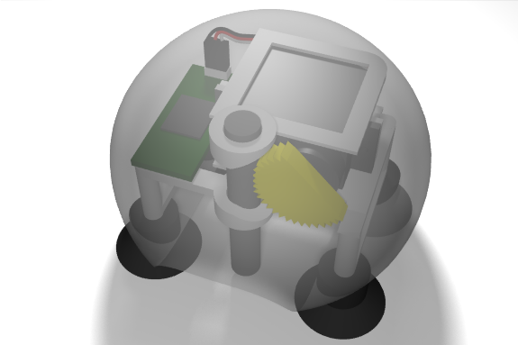
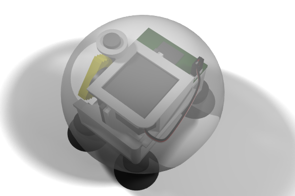
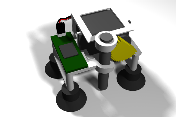
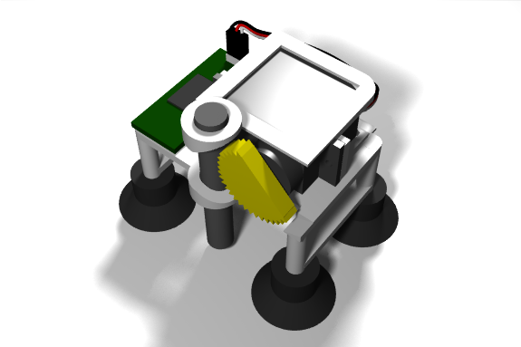
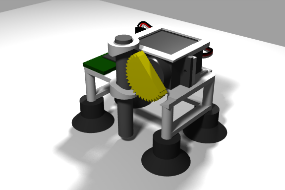
Still I was able to capture a few renderings of the design before it all evaporated. They are all that’s left.
I chose to focus on the mechanical aspect of the Remotable. So visually it may not be very appealing.
The sphere is half transparent to display the internals of the device and its operation. I believe the users will actually have fun seeing the mechanics work.
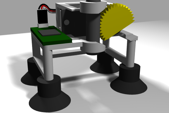
Inside the case we see the frame (plastic), servo, gears, shaft, PCB and suction cups.
The shaft (aluminum probably, to reduce friction) is braced to the frame tightly, and motorized by the gear. Grooves on the shaft allow a linear motion up and down.
I chose to use four 6lbs-load suction cups to hold the Remotable down to the surface. This limits its abilities to stick to any surface.
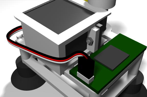
I had free space to the left of the servo, and since I didn’t want to put anything below or above the servo, I used this free to place the PBC and some wiring.
The servo is tightly screwed into place in the frame to maximize transfer of force from the shaft to the suction cups. It’s wires connect to the PCB with a standard connector.
The space under the Remotable is reserved for objects that will go under it (to be pushed upon).
But like we say back home: “You don’t cry over spilled milk” and “You can’t put toothpaste back in the tube”, so – back to the drawing board!
