Generally, “DIY” class or kit-class quadrotors are sized to use common R/C model aircraft components – a kit frame from a company such asMikrokopter or Hobbyking is sized for any of several different types of motor in a certain size range (which generally shares the same mounting flange dimensions).
One look on Hobbyking shows that there are 11 total pages of products in the small outrunner motor category, and 26 unique products in the small motor controller category. This represents one extreme of customizability – it is, arguably, not a product at all, but an experience. The user has to have some existing knowledge of the end result to even know what they need to buy. Just mixing and matching the possiblities might not result in a configuration that works – the motors might be too powerful for the controllers, the propellers might be wrongly sized for the motor, or similar.
A “kit business” like Mikrocopter represents customization at the product level. Different combinations of the same parts are turned into different whole products. Compare their octocopter versus their hexcopter: quite literally the same motors and same propellers, just a different number. The propulsion modules are standardized, the arms/booms are standardized, and only the control board and the center “hub” changes with the number of arms. However, those are different products in and of themselves – a 4-boom quadrotor cannot be converted to a 6-boom hexrotor just by adding more motors. The geometry is totally different, as are the specific algorithmic implementations in the controller.
What sets the Chibicopter project apart from either of those two examples is that it occupies a special niche in the hobbyist UAV design space. The parts required are inherently niche – they are designed for use in micro- and indoor-flying models. There are not many selections. In fact, there is exactly one motor available in the size and weight required for the project (the 2 gram outrunner), and its mounting scheme (a single tube) is very unconventional. The choice of controller is limited to only three (and they are essentially different brands of one OEM). The goal of the project is to create the smallest quadrotor using commonly available, easy-to-buy components, so while I could easily hire out a manufacturer’s services to build me four different power and speed versions of the above 2 gram motor, that does not qualify for the design goals.
There are several ways that the Chibicopter project can be altered which I contend do not constitute variations on the same product, but wholly separate products or concepts.
Allowing flexible motor types is not a variation of the current design
The only other motors available in the single digit grams weight class (e.g. the 2.3, 3.1 gram and the 5 gram motor) use a different flange-based mounting scheme. While it can be reasonably argued that the 2.3 and 3.1 could have been selected instead of the 2 gram, pole-mount motor, the former was not in stock at the time of selection (and in fact is still not). Given this constraint of materials and time, the design was optimized towards the 2 gram motor. A completely different arm design would be needed to adapt to the other motors, and this would constitute a separate independent product because the arms are integral to the entire airframe.
Allowing differing number of arms is not a variation either
The airframe of Chibicopter is a single-piece 3D printed object. Like the Mikrocopter modular frame, there cannot be post-appending of more arms onto the center, only replacement or repair. The spacing would be incorrect and the propellers would collide with eachother should I just allow “circular pattern copy and paste”. Therefore, any design variation allowed must come before production begins. In a hypothetical world where I market Chibicopter kits, a six rotor frame is therefore an entirely separate product – much like Mikrocopter’s six and eight rotor frames. Different control boards must also be designed, assembled, and tested for different rotor counts.
In this case, the general idea of what constitutes customizing Chibicopter vs. building an entirely new one is that the result still outwardly resembles a version of the product which is described as “Stock” or “original”. There are then several modifications which are easy to make and do constitute variations:
R/C receiver input vs. XBee input
Because the XBee module is so large and itself very integrated, all it needs is a set of headers on the main PCB. R/C receivers for micro and indoor fliers exist in small enough sizes to fit within the set of headers. Therefore, it would be easy enough to create the logic to accept either type of input – four R/C servo channels, or one serial stream from the XBee. These may all fit onto the same board, as the receiver would just need signal headers of its own which can be placed to not interfere with the XBee headers.
This is a true usage customization because it allows the end user to choose either communication method at any time. The code may even automatically detect and switch – if it detects R/C servo pulses, then it will default to those. If it instead receives data over UART, then it will interpret those. Having both means at once is not a stretch if the physical volume is available – which is uncertain at this point in the product development process.
Different propeller size and pitch
The 2 gram motor specification indicates that it is matched to a type 3020 propeller: 3″ diameter, 2″ pitch. The propellers that I have selected for the current design are type 2510, 2.5″ diameter and 1.0″ pitch. It is common practice to “underprop” a quadrotor motor, because quadcopters spend their time statically hovering instead of moving forward briskly, reducing the motors’ opportunity to air cool. Additionally, lightly-pitched propellers generate more static thrust than their highly pitched variants, but need to be run at higher speeds to do so: a fast motor with a lightly pitched prop makes for a quadrotor with snappier response.
It can be seen that I am “underpropping” my motors. Conceivably, moving up to 3 inch propellers will make for a Chibicopter with much more thrust and lifting capacity, perhaps opening up the design to carrying very small cameras, or allowing it to perform acrobatics with the increased thrust overhead. The 3 inch propellers indicated on the motor page as a good performance match are also physical matches – their bores are the same as the 2.5″ type propeller.
Therefore, it can be a usage customization to change propeller sizes. However, there is a limitation – the as-designed airframe can only host 2.5″ propellers, as 3 inch props would interfere at their tips. This issue will be addressed shortly.
Different arm lengths may be a variation
There can be several reasons to increase the armspan of a quadrotor. As just described, fitting larger propellers is one reason. Second, the wider the arms of the quadrotor, the more leverage the propeller thrust has on the center of gravity, and thus the system can be made more stable. The only downside is added weight and eventual violation of allowed flexibility or stiffness design rules because the longer arms are “floppier”.
Given the 3d printed nature of the fuselage, different arm lengths are indeed possible. However, this is once again a production stage customization, and perhaps it is easier to argue that Chibicopters with 75mm arms vs. 110mm arms are different products.
One way to get around this is to have the frame not be single-piece printed, but have the arms themselves as separate pieces. Then, it would be easy to have a run of many standard parts printed, but have them be interchangeable. Strange combinations like orthorhombic quadrotors (where one diagonal uses shorter arms) would be possible. As long as the number of arms stays the same, the control algorithm does not need to change, only the control gains – a matter of software, which is inherently configurable.
The production of this design would not need any variations in parts in order to meet all of the possible usage customizations it affords.
Therefore, the maximally customizable Chibicopter is:
A center fuselage housing the multimodal communication board (R/C or XBee) with dovetail grooves or snap-on attachment points which can interface with several different length arms, all of which mount the 2 gram type outrunner but can take propellers between 2″ and 3″.
To address the questions directly:
1) The most likely customer of Chibicopter is a small UAV enthusiast who has some background in multicopters and who wants to experiment with very small ones.
2) All of the qualified customizations are usage-level customizations. Should the fully-customizable design be produced, then the PCB and airframe are all of one design that can be assembled differently without being detrimental to the product operation. Otherwise, given the current design, only the propeller size and multimodal communication constitute customizations (The arm length is fixed because the frame has been ordered already, and no other motors exist in this form factor)
3) At the simplest level, they do not. The PCB remains the same no matter if Chibicopter has 75mm or 110mm arms. The 3d printed parts can be made in large batches with no changes. However, differing arm lengths and differing prop sizes will require changes to the system control gains. This is purely a matter of user preference (higher gains are less stable, but perhaps more suited to acrobatics as a result). This latter constraint applies to the current Chibicopter iteration as well.
4) If the airframe itself is considered to be one component (since it is supposed to be one unit during operation no matter how snap-together or customized), then there are ten functional components:
- The airframe itself must be structurally integral and be able to handle thrust loads and probably impacts too.
- Four motors, each of which have to be consistently manufacturered to deliver the same speed and torque
- Four propellers, which have to be balanced, properly fitted to the motors (no falling off), and be… not broken
- The control unit is considered as a single assembly which either works to control the motors properly, meaning it is well-tuned, manufactured with no errors, and is operating within specification (battery voltage, system gains, etc.), or does not, in which case the copter does not fly properly.
If the control unit is broken down into its own parts, then the whole system has fifteen functional components, which now include
- The board itself: manufactured without errors
- Four motor controllers which must have the same command-to-output characteristics
- The IMU (inertial measurement unit) which must give clean and accurate attitude and heading information.
A Parametric Chibicopter
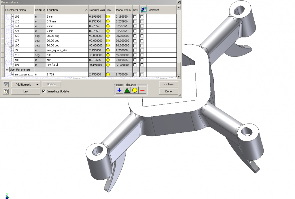
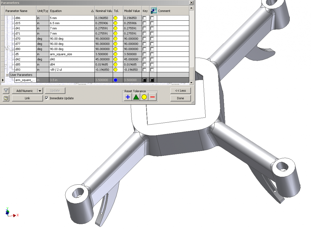
Chibicopter is designed in Autodesk Inventor, which is inherently a parametric CAD software, so really most aspects of it are already “parameterized”. However, to address the different arm lengths, it is easy to set an explicit variable to control it:

 The latter arm span can support either 3″ props or 2.5″ props – perhaps this is a better design for the revision!
Liaison Diagram for Chibicopter
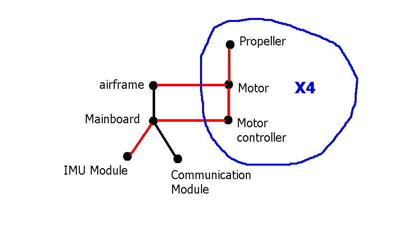
The Liaison diagram for Chibicopter is very straightforward, as it is a roughly linear assembly of mechanical components. Red relations mark critical mates in the assembly – e.g. if the motor is not mounted solidly in the frame, the copter will not fly well (and the motor could fall off!). Same goes for the props – they must be centered and balanced. The electrical connection between motor and controller is, of course, critical, as is the connection of signal between controller and mainboard. And so on…
 However, the mainboard is welcome to sit in the airframe with significant variation – hence, it is a contact, not a mate.