Parts List
Enclosure (colored plastic, custom made (injection molding?), likely < $3 total):
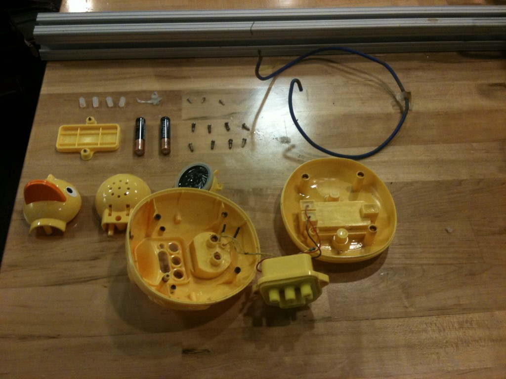
- Upper duck body
- Lower duck body
- Duck head front
- Duck head back
- Duck head middle (speaker holder)
- Duck beak
- Duck battery Cover
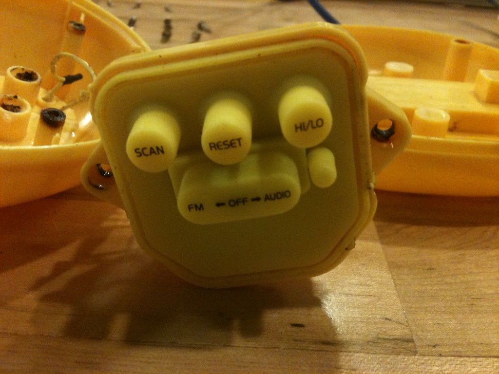
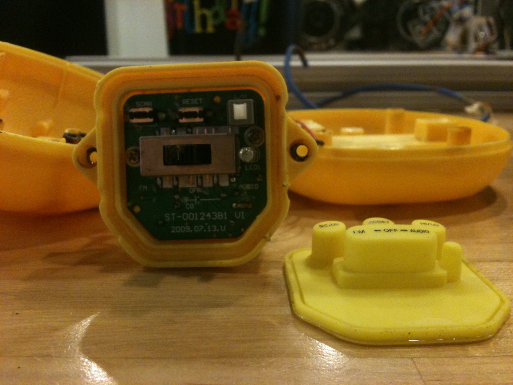
- Control panel enclosure
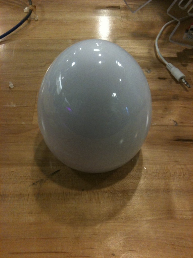
- Egg top
- Egg bottom
- Egg battery cover
Water Proofing:
- 4x Screw Hole plugs (transparent rubber, custom made (mold?), < 1 cent each)
- Duck body o-ring (transparent rubber, custom made (mold?), < 1 cent)
- Control panel cover (molded rubber, < 1 cent)
- Hot glued joints (hot glue, manually applied, < 1 cent total)
Fastenings:
- 19 screws (standard parts, any hardware supplier, < 1 cent each)
Electronics (standard components from mouser or digikey?):
- 1x audio cable (< $1)
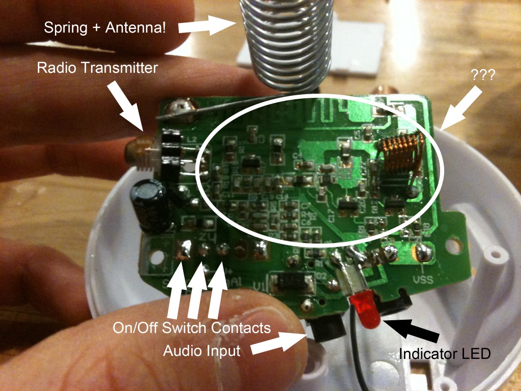
- 1x antenna (< $1)
- 1x antenna resistor (< 1 cent)
- 7x wires (< 1 cent each)
- 1x small speaker (< $1)
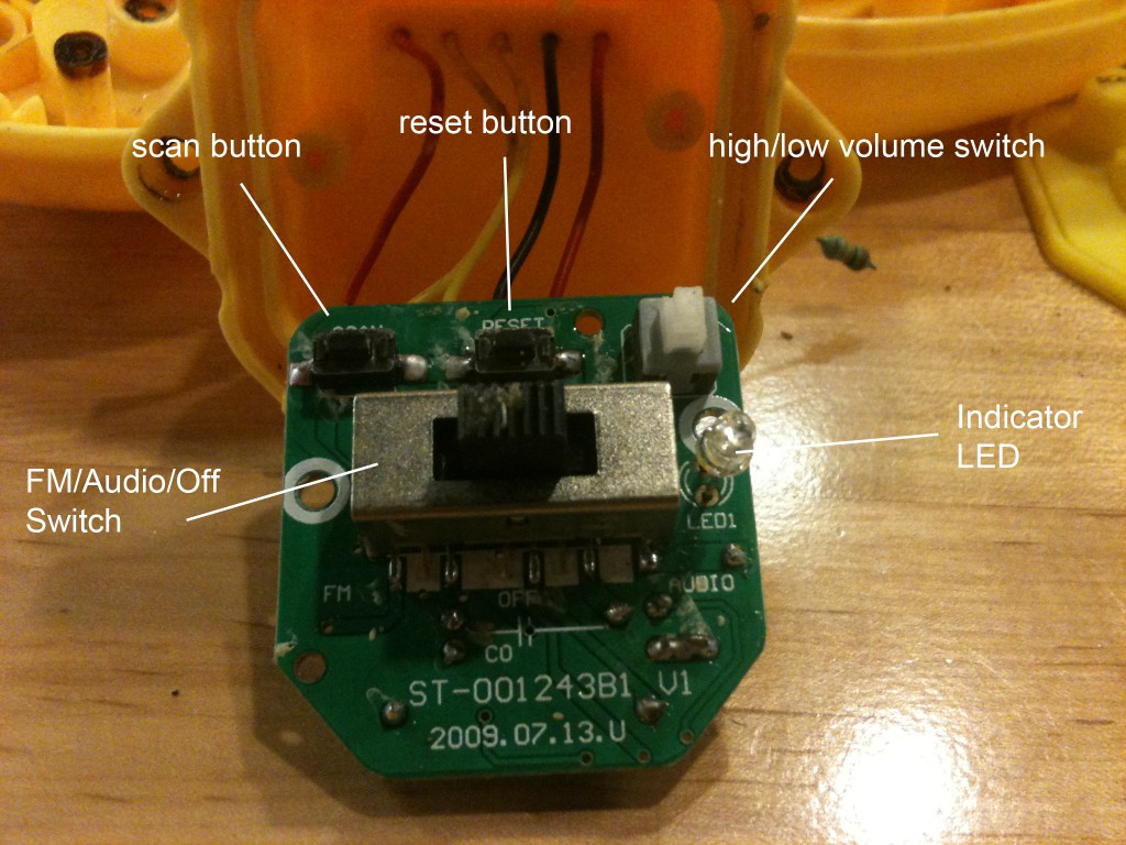
- 3x buttons (< 1 cent each)
- 1x three-way switch (duck, < 1 cent)
- 1x two-way switch (egg, < 1 cent)
- 2x indicator LEDs (< 1 cent each)
- Many SMD resistors (< 1 cent total)
- Many SMD capacitors (< 1 cent total)
- 4x inductor coils (< 1 cent total)
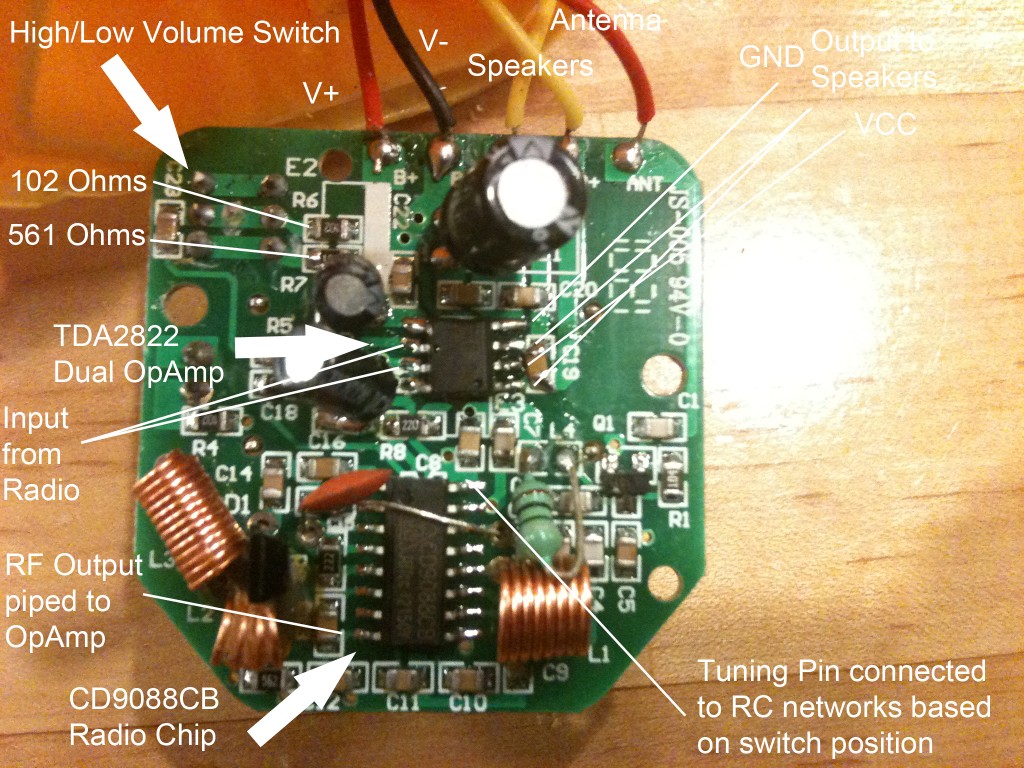
- TDA2822 dual op-amp (< 1 cent)
- CD9088CB radio chip (< 1 cent)
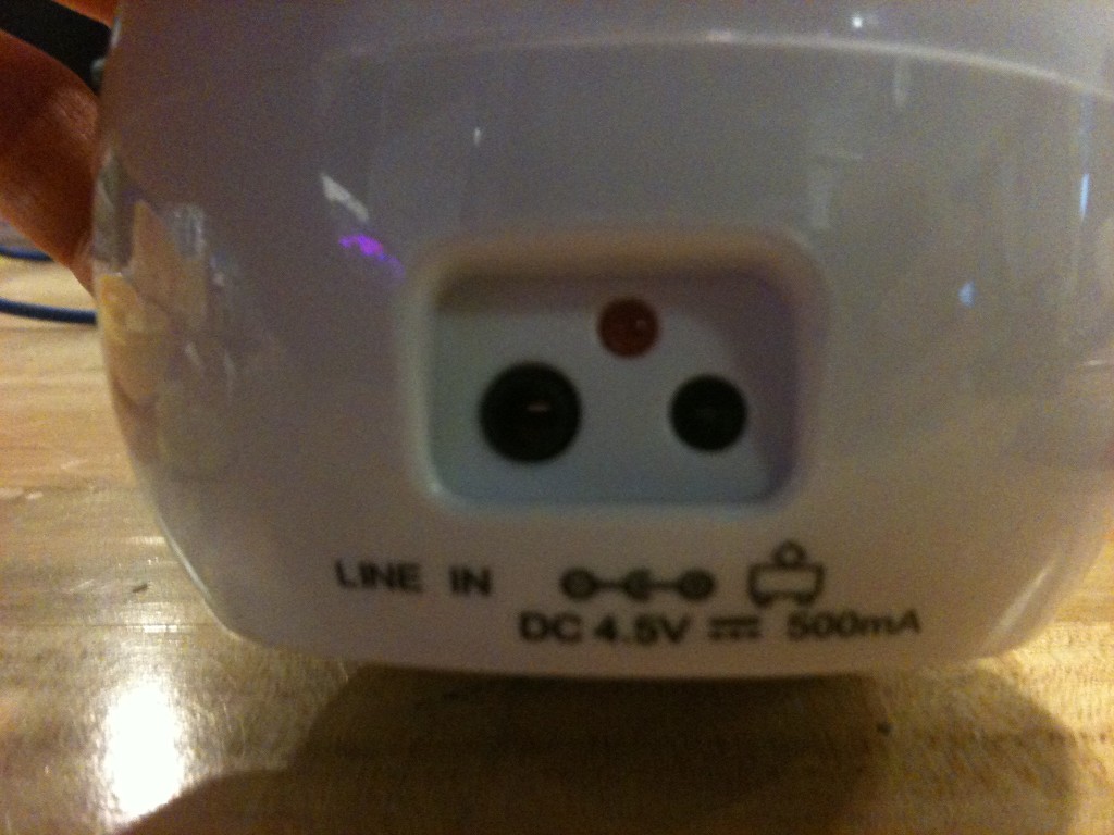
- 1x audio jack (< 1 cent)
- 1x power jack (< 1 cent)
- 1x radio transmitter (< 1 cent)
- 1x antenna spring (< $1)
- 2x silicon chips (< 1 cent each)
Assembly Sequence:
- Injection mold duck body, duck head, control panel case, etc. (automated)
- Vacuum mold control panel cover (automated)
- Surface mount solder electrical components and wires onto silicon boards (automated)
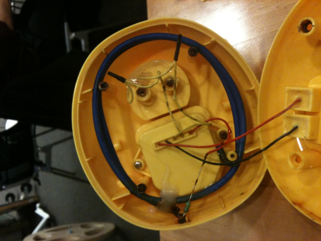
- Put duck chip in control panel case (screws), thread wires through back, thread battery wires into battery case, thread speaker wires into duck head, solder battery wires to battery contacts, solder speaker wires to speaker, solder antenna wire to antenna resistor and antenna. (manual, solder, hand-held soldering iron)
- Screw in duck beak, screw speaker to middle duck head piece, screw duck head front, middle, and back together. (manual, screws/screwdriver).
- Screw duck head to upper duck body, place o-ring in duck body, place antenna in duck body, place control panel in duck body, screw on duck bottom to duck top, screw in duck battery cover. (manual, screws/screwdriver).
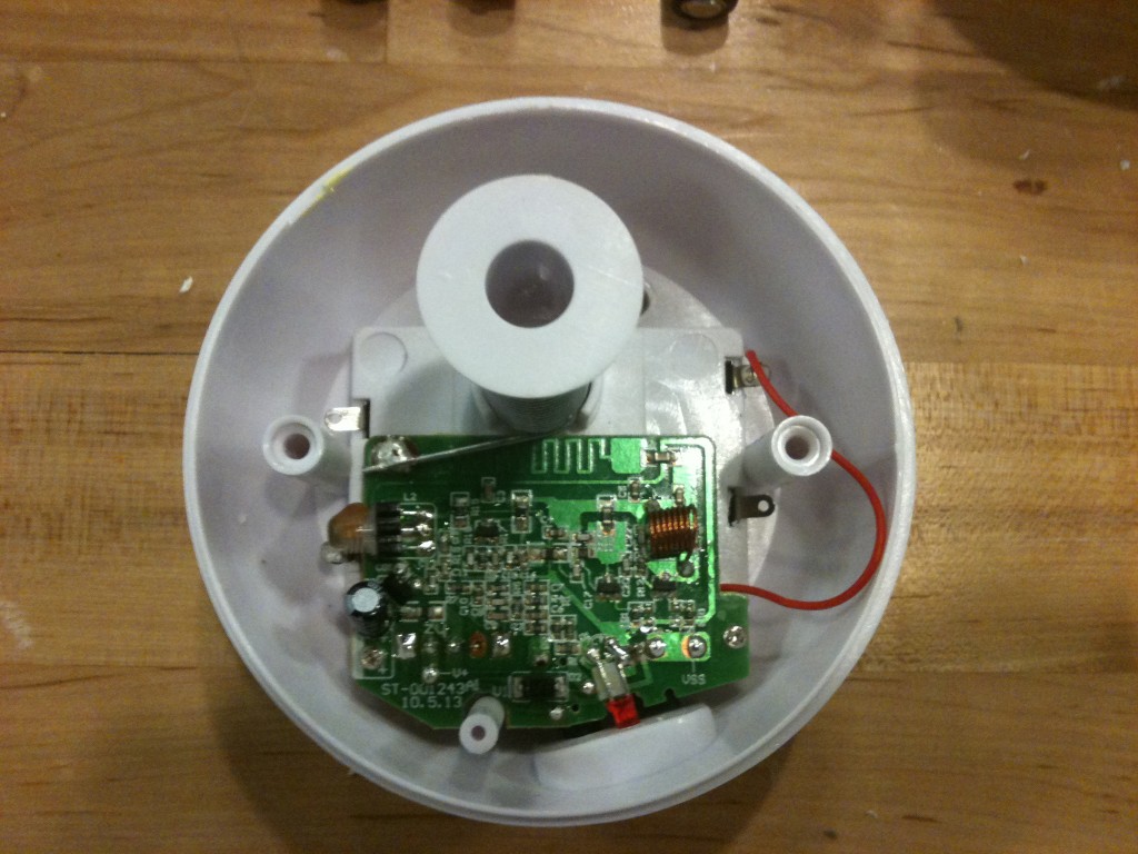
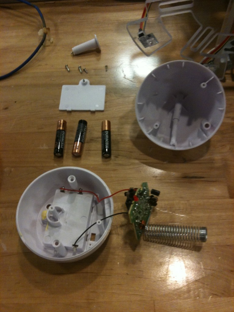
- Place egg chip in egg, solder battery wires to battery contacts. (manual, solder, soldering iron)
- Screw on spring antenna cover. (manual, screws/screwdriver)
- Screw egg top onto egg bottom. (manual, screws/screwdriver)
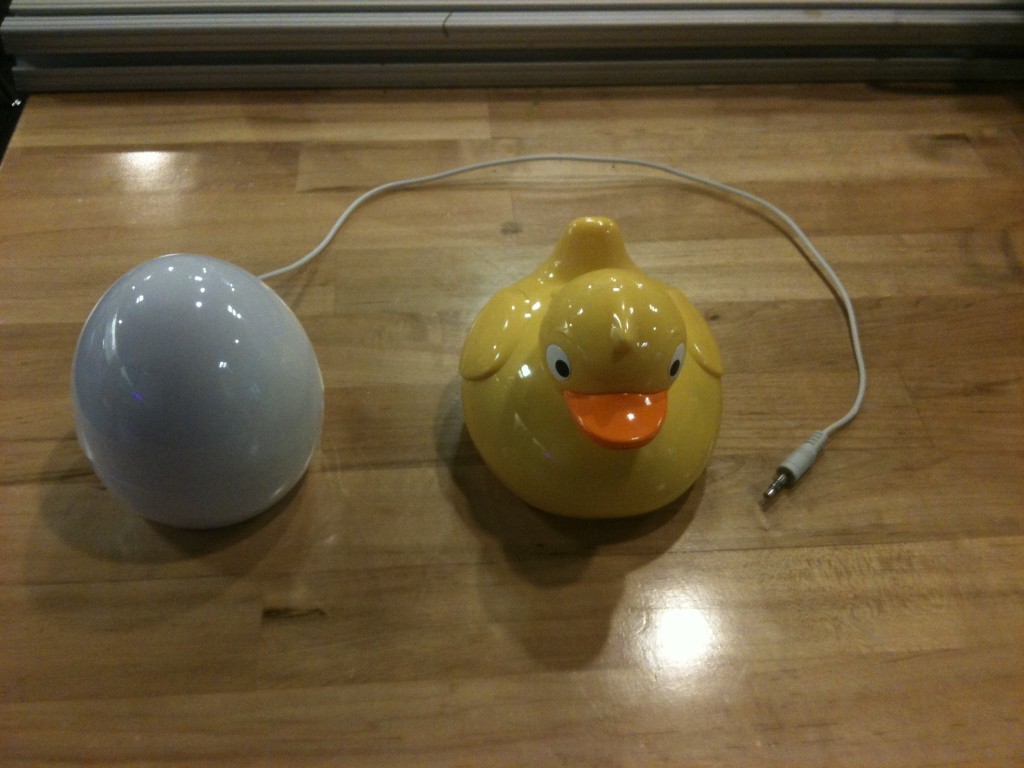
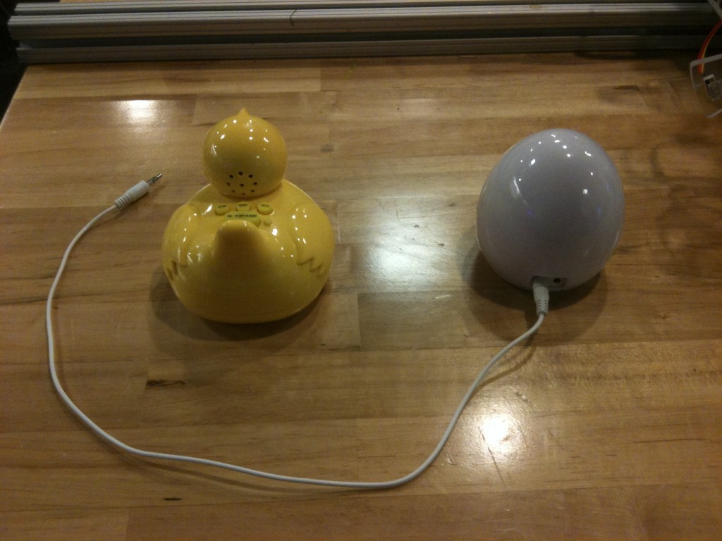
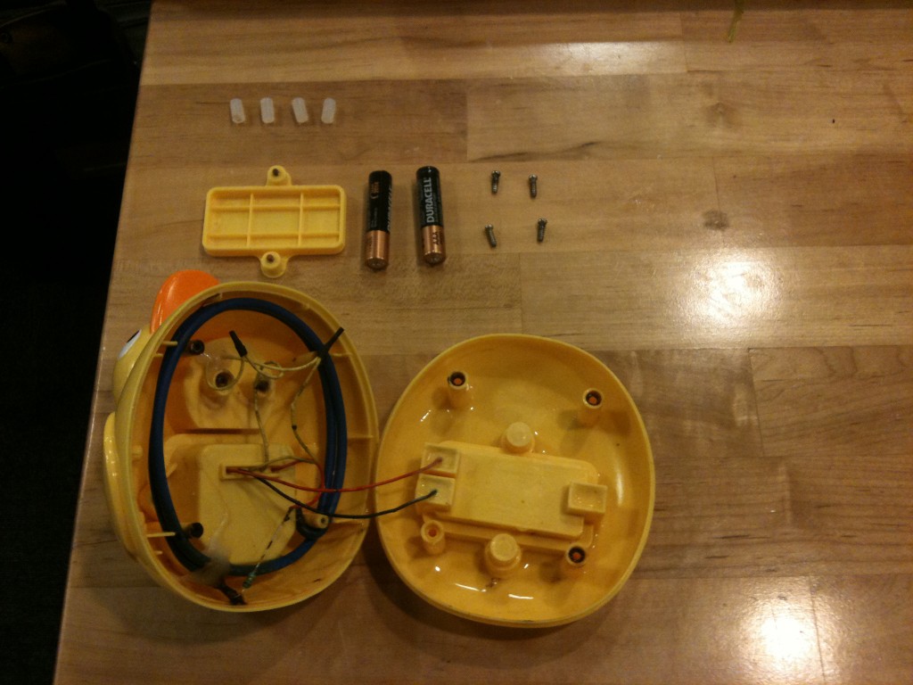
Shaun,
Would be interesting to make a comment regarding the difficulty of step 4 in the assembly sequence. Did you have to first put the duck chip in the case and then solder the cables or vice versa? Was there any part that could be redesigned to assist assembly and cable soldering? Where there any jigs used?
What was the purpose of liquid silicon? to temporarily hold cables during assembly or to permanently fix stuff? Could it be replaced with a different design detail of the part? Was it a mistake of the designers that they just didn’t think of during design?
Would be useful to try to make a graph of the assembly sequence and locate the steps of higher/lower difficulty. How much time did the assembly take?