Oh, well. Not particularly. I cobbled together a number of components to put together a bit of bric-a-brac that rides around in your bicycle with you.
Parts:
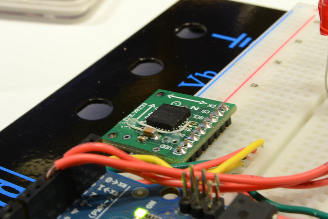
- LIS3LV02DQ Sensor on a Sparkfun breakout board
- Momentary Switches
- Red LEDs x 3
- Assorted current-limiting and pull-up resistors
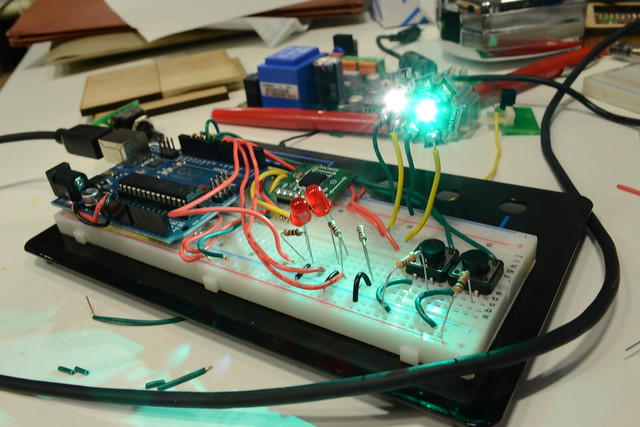
- Crazy-bright Luxeon Mega-LEDs
- Little bits of wire zipping around
- Arduino Uno
Construction Challenges
I2C is a real challenge if you haven’t done it before. I have not done it before–so naturally enough, first I failed. I played around with an analog version of the sensor (ADXL322), but it’s only dual-axis–and also, it worked too easily, so that’s so fun. I never got the I2C interface working–but I’d like to give it another shot. I did manage to get a version working with SPI, which is certainly good enough for my purposes.
LIS3LV02DQ Sensor on a Sparkfun breakout board
Bike Signals
These Luxeon Rebel on Mega-LEDs will destroy your retinas. They’re fairly expensive, but in this form, come mounted on a heat-dissipating PCB, so they’re really easy to use. They’re big power draws, slurping something from 350mA to 700mA, so power will be a major issue. If I want to use this kind of LEDs (I’d only need a couple), the power draw will be substantial. For, say, four LEDs, I’d be running at something like 12V @ 500mA, which will tear through some rechargeable LiPos really quickly. I might consider other (cheaper) LEDs that will work just as well — though I like the idea of blinding light.
Ultimately, of course, these bright LEDs will correspond with the accelerometer in some yet-to-be determined way.
Power
If I want to use this kind of LEDs (I’d only need a couple), the power draw will be substantial. For, say, four LEDs, I’d be running at something like 12V @ 500mA, which will tear through some rechargeable LiPos really quickly. I might consider other (cheaper) LEDs that will work just as well — though I like the idea of blinding light.
Sensor Readings
I took some readings with the sensors on my bike ride home last night — it was a bit squashed in my backpack, so they didn’t come out wonderfully. Also, the orientation was off, as I couldn’t put the sensor-board flat in my back–so the X-axis is actually up-and-down — and the z-axis corresponded with the axis of motion. For some reason, it didn’t seem to give any good values, which is a problem, as that’ll be a critical axis to capture for braking and acceleration. I’ll post some higher-fidelity results later, as the sensor works not awfully. Basically, I cannot make sense of these readings at all, so that’s one challenge.
Y-Axis Readings. I have no idea what this means.

X-Axis Readings: Moving up-and-down (so secretly, z-axis)

Getting good sensor readings out of this will take some experimentation, perhaps using the interrupts and such–so that we’re only triggered on collisions and the like. Once the LEDs signals are integrated with the accelerometer, behavior can change when you’re turning. Conversely, the accelerometer can detect when you’re turning and signal automatically. That’d be nice too. Many thoughts. We’ll see.